00 — Knee Rehabilitation Exoskeleton · Research

An ultra-low-cost,
semi-rigid cable-driven
knee exoskeleton.

Designed for equitable orthopedic rehabilitation in low- and middle-income countries — the world's missing five billion patients. Self-aligning to the knee's instantaneous center of rotation, repairable with 3D-printed spares, and explained end-to-end below.

$200
Bill of materials
0.85kg
Total mass
13.5Nm
Peak torque
0–145deg
Range of motion
82%
AI · PT agreement
2.2h
Runtime
01Problem

The two cheap alternatives fail biomechanically; the powered ones are unaffordable by an order of magnitude.

ACL ruptures, meniscal tears, and degenerative knee osteoarthritis account for more than half of global lower-limb disability-adjusted life years. Roughly five billion people lack timely surgical access; conservative management is their only option.

For those patients, two cheap options exist — elastic compression sleeves that deliver no therapeutic torque, and rigid post-op braces that misalign with the knee's migrating center of rotation, generating constraint forces and skin shear. The third option, robotic exoskeletons (ReWalk, Ekso, Roam) deliver real torque but cost between US $7,000 and US $100,000.

LMIC per-capita health expenditure routinely falls below US $200 per annum. The disparity is not a market gap; it is a structural exclusion of the highest-need populations from the highest-impact technology.

Field gap A device that costs the same as a brace, delivers the torque of a powered exoskeleton, and aligns with the joint at every angle does not yet exist.
02Approach

Rigid, soft, or semi-rigid. The third path resolves a real trade-off.

FIG · DESIGN SPECTRUM RIGID motor misalign @ flex. SOFT EXOSUIT force leaks SEMI-RIGID CHAIN motor @ hip tracks ICR stable l_a
Fig. 2.1 Rigid systems impose torque but fight the joint; soft suits track the body but bleed force through fabric; the chain does both.
A · Rigid frame

Hospital-grade. Heavy. Misaligned.

Aluminum or steel exoskeletons with electric or hydraulic actuators at each joint. Strong, precise, repeatable — but assumes a simple hinge knee, ignoring the joint's translational motion. Slight axis offsets become shear forces and pressure injuries.
+ Deterministic torque · 13–40 Nm
+ Precise joint angle control
− Donning time 30–40 min
− 18–25 kg full-limb mass
− Misalignment shear at the knee
Cost
$70k–100k
Mass
18+ kg
B · Soft exosuit

Light. Comfortable. Underpowered.

Textile sleeves with Bowden cables or pneumatic actuators. Conforms to the body — no rigid axis, no misalignment. But the fabric stretches; force leaks through unwanted motion; pressure concentrates on the patella when straps cinch tight.
+ Conforms naturally to body
+ Lightweight, portable
− Peak knee assist ≈ 0.03 Nm/kg
− Unstable moment arm
− Patellar pressure points
Cost
$2k–7k
Mass
2–4 kg
C · Semi-rigid chain — this work

A third path, drawn from Exo-Muscle.

A segmented chain wraps the posterior knee — flexible when unpowered, rigid when the cable tensions. It creates a temporary external joint that moves with the knee, giving a defined cable path for deterministic torque without imposing a fixed hinge.
+ Self-aligning · 1.39 mm mean offset
+ Hip-mounted actuator (250 g distal)
+ Field-repairable PLA spares
+ Distributed strap anchoring
Cost
$200
Mass
0.85 kg
03Biomechanics

The knee is not a hinge. It is a rolling, sliding J-curve.

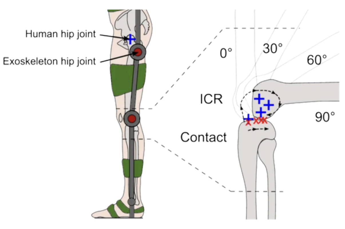
During flexion the femoral condyle rolls and slides on the tibial plateau, shifting the instantaneous center of rotation posteriorly and inferiorly. Any device built around a fixed pivot will fight the joint at every angle.

FIG · J-CURVE OF THE ICR femur tibia θ = 0° θ = 30° θ = 60° θ = 90° J-shaped ICR path POSTERIOR · INFERIOR DRIFT x y
Fig. 3.1 The ICR migrates ~25 mm posteriorly and inferiorly between full extension and 90° flexion.

The instantaneous center of rotation (ICR) is the point about which one segment of the knee is, at that instant, purely rotating. Unlike a pin joint, the ICR is not fixed: the geometry of the condyle–plateau contact, combined with ligament constraints, traces a curve we can describe as J-shaped.

The cable's moment arm la — the perpendicular distance from the ICR to the cable line of action — is what converts cable tension into knee torque. If la collapses, so does the assistive effect. Our chain geometry is calibrated to keep la stable across the full 0°–145° range.

Texo = Ftendon · lakf) Eq. 3.1 · Knee Torque

For real-time control, the moment arm is fitted to a fifth-order polynomial of the knee flexion angle, avoiding the cost of a per-frame analytic solve. MATLAB simulations show la decreases mildly from 0°–30°, then increases monotonically past 30° — a useful asymmetry that biases assistance toward the strenuous phases of squatting and stand-to-sit.

la(θ) ≈ −2.27·10−12 θ5 + 1.10·10−9 θ4 − 2.46·10−7 θ3 + 2.87·10−5 θ2 − 1.01·10−3 θ + 0.074 Eq. 3.2 · Polynomial Fit
FIG · MOMENT ARM vs. KNEE FLEXION ANGLE 0.100 0.088 0.076 0.064 0.052 0.040 l_a [m] 30° 60° 90° 120° 145° knee flexion angle θ_kf min @ ~30° max @ ~120° 5th-order polynomial MATLAB sim · n = 10
Fig. 3.2 The moment arm dips at 30° (a low-load phase) and peaks near 120° — the strenuous deep-flexion zone where assistance helps most.
Key finding · 3
The semi-rigid chain tracks the J-curve ICR with a mean misalignment of 1.39 mm and an RMS misalignment of 2.55 mm across the full 0°–145° range — versus typical fixed-hinge errors of 10–15 mm at deep flexion.
04Mechanical design

A single cable, four anchor points, and a chain that becomes a joint on demand.

Power flows from a hip-mounted brushed-DC actuator, through a Dyneema cable, into a segmented chain wrapping the posterior knee, and out through four distributed straps that share load across the thigh and shank. The chain locks rigid only while the cable tensions; otherwise the user moves freely.

FIG · SYSTEM ARCHITECTURE · POWER & LOAD PATH hip / waist BACKPACK MOUNT thigh knee shank DH03X · 20:1 ESP32 · BT18 · LD3320 HX711 A · ACTUATOR DH03X brushed DC + 20:1 spur gearbox τ_peak = 13.5 Nm · P_max = 95 W B · CONTROLLER ESP32 · BT18 · LD3320 voice f_loop = 2 Hz · PWM motor drive · Wi-Fi C · TENDON + SENSOR Dyneema cable · HX711 load cell MBL ≥ 1200 N · SF = 3 · ±0.8 N RMSE D · SEMI-RIGID CHAIN 13 PLA links · transverse k > 50 N/mm Clearance ≥ 3 mm · 3D-printed spares E · IMUs (×2) MPU-6050 · thigh + shank Δθ_RMSE = ±0.8° · differential kinematic F · DISTRIBUTED ANCHORS 4 PETG cuffs + nylon straps p_skin ≤ 20 kPa · comfort 4.1 / 5
Fig. 4.1 The entire load path from motor spool to leg anchors. Distal mass — everything below the hip cuff — totals ≤ 250 g.
04.2 · Mass budget
SubsystemMaterialMassPosition
Actuator module
DH03X + gearbox + spool
380 g hip
Controller cavity
ESP32, BT18, LD3320, battery
220 g hip
Thigh frame
2 rails + 2 cuffs
Al 6061 + PETG 110 g thigh
Shank frame
2 rails + 2 cuffs
Al 6061 + PETG 95 g shank
Semi-rigid chain
13 PLA links + pins
PLA 38 g knee
Dyneema cable
incl. Bowden sheath
UHMWPE 9 g routed
Sensors
2× MPU-6050 + HX711
12 g limb
Total mass 0.85 kg
Distal mass (below hip) ≈ 264 g — three orders of magnitude below comparable rigid platforms (ReWalk ≈ 22 kg total, ≈ 9 kg distal).
04.3 · Free-body diagram
ICR F_cable l_a τ_exo m_shank g τexo = Fcable · la(θ) where 0.057 ≤ l_a ≤ 0.080 m design target: τ ≥ 10 Nm · F ≈ 400 N
Fig. 4.2 Cable tension resolves at the chain's tangent point; the moment arm la is what we control.
05Hardware

Commercial off-the-shelf, throughout — total electronics under $150.

Eight components do everything: one microcontroller, two IMUs, one load cell, one motor + gearbox, one Bluetooth radio, one voice chip, one Dyneema cable. Each was chosen to be procurable at a community electronics market.

A · Main controller

ESP32 microcontroller

Runs the 2 Hz control loop, the closed-loop torque regulator, Wi-Fi telemetry to the dashboard, and the Bluetooth/voice command stack. Open hardware, abundant in low-resource markets.
Cores · Xtensa LX6 × 2 @ 240 MHz
I/O · 34 GPIO · PWM × 16
Radio · Wi-Fi b/g/n + BT 4.2
Cost · ≈ US $8
B · Kinematic sensing

Dual MPU-6050 IMUs

One on the thigh rail, one on the shank rail. A differential measurement of orientation gives knee flexion angle and angular velocity directly, avoiding magnetometer drift.
DoF · 3-axis gyro + 3-axis accel
Range · ±2000 °/s · ±16 g
Bus · I²C · 400 kHz
RMSE · ±0.8° vs goniometer
C · Force sensing

HX711 load cell

Inline with the Dyneema cable between spool and chain. Streams cable tension into the controller; tension × moment arm gives true assistive torque, the basis for closed-loop regulation.
Range · 0–500 N
Resolution · 24-bit
Rate · 80 Hz
RMSE · ±0.8 N · target < 2 N
D · Actuator

DH03X DC motor + 20:1 spur gearbox

Brushed DC, hip-mounted in a backpack bracket. The 20:1 reduction amplifies motor torque into the cable; a 35% safety margin sits above the 10 Nm design target.
τ_peak · 13.5 Nm
P_max · 95 W
Spool r · 0.025 m
Drive · PWM via L298N
E · Tendon

Dyneema UHMWPE cable

Routes from the spool, through a Bowden sheath, into the semi-rigid chain on the posterior knee. MBL gives a tensile safety factor of 3 at design tension.
Diameter · 1.8 mm
MBL · ≥ 1200 N
Friction η · 0.92
SF · 3 @ F_design 400 N
F · Wireless

BT18 Bluetooth module

Connects the device to the mobile/web dashboard for mode switching, parameter tuning, and live data viewing. Low-bandwidth — only command + acknowledge.
Bus · UART · 9600 bps
Range · ~10 m
Power · 30 mA peak
Pairing · SSP
G · Voice interaction

LD3320 offline voice chip

"Hey Regenix" wake word, then a 30-second command window for mode switching, status query, and emergency stop. Offline — no network dependency in clinics with weak connectivity.
Accuracy · ≥ 95% quiet · ≥ 90% noisy
Latency · ≤ 500 ms
Commands · 6 mapped
Cost · $15–20
H · Safety

Mechanical e-stop latch

A spring-loaded latch on the spool that the user can release to instantly slack the cable, decoupling the device from the limb regardless of microcontroller state. The highest command priority.
Response · < 50 ms
Action · Cable slack
Mode · Mechanical
Reset · Manual
I · Power

Lithium-ion battery pack

A 2000 mAh, 11.1 V pack in the hip cavity drives the motor and electronics; a planned 5000 mAh upgrade plus solar charging is documented under 10 Outlook for LMIC field deployment.
Capacity · 2.0 Ah
Voltage · 11.1 V (3S)
Runtime · 2.2 h
Charge · 3.5 h via USB-C
05.2 · Hardware benchmark scorecard
Metric Design target Measured Status
Cable force RMSE < 2 N 0.8 N Pass
Knee angle RMSE < 1° 0.8° Pass
Peak motor torque ≥ 10 Nm 13.5 Nm Pass +35%
Battery runtime ≥ 2.0 h 2.2 h Pass
Total mass ≤ 2 kg 0.85 kg Pass · 58% under
Bill of materials < US $200 ≈ US $200 Met
Donning time < 60 s ≤ 30 s Pass
Voice command latency ≤ 600 ms ≤ 500 ms Pass
Joint misalignment (mean) < 5 mm 1.39 mm Pass · 3.6× under
06Rehabilitation modes

Four modes covering the whole rehabilitation arc — early passive recovery to late strength training.

Modes switch via the mobile dashboard, Bluetooth, or the offline voice channel. Each maps to a specific clinical phase and a specific torque-or-resistance regime; the controller blends sensor signals to keep the patient inside a safe operating envelope.

01
Early postoperative · Phase I–II

Assistive training

The motor actively drives the cable to generate 2–10 Nm of assistive torque, smoothly modulated based on detected motion phase. The patient regains baseline ROM with minimal voluntary effort while a series-elastic element buffers transient loads.

Torque band
2 – 10 Nm
Trigger
IMU phase
Goal
Restore ROM
Use
Week 1 – 4
02
Early-to-mid · Phase II–III

Protective (threshold-gated)

Assistance only activates when user-generated force exceeds a configurable threshold. Encourages active participation while still catching the patient if the muscle fatigues — a moderate 3–8 Nm assist completes the motion.

Torque band
3 – 8 Nm
Trigger
F_user > F_th
Goal
Active assist
Use
Week 4 – 8
03
Mid-to-late · Phase III–IV

Resistive · impedance

Inverts the cable: the motor applies a resistive torque proportional to user effort × moment arm. Fatigue is detected via IMU signal variance; resistance backs off automatically when tremor-like oscillations exceed threshold.

Resistance
∝ F_user · l_a
Trigger
user motion
Goal
Strengthening
EMG
+15 – 20% activation
04
Assessment · all phases

Test & evaluation

Motor is passive; the device becomes a measurement instrument. Synchronized force, angle and angular velocity streams flow into the on-device analytics pipeline (07) and out to the clinician dashboard.

Motor
passive
Channels
3 @ 2 Hz
Tests
MVE · cycle
Outputs
stat · cluster · score
07AI pipeline

From raw force/angle traces to a personalized recommendation, in five deterministic steps.

The analytics platform is Python + SQLite, running on the same hardware as the dashboard — a single Raspberry Pi or community-clinic laptop. Statistical and clustering modules are deterministic; only the final recommendation passes through a language model, and only after the raw signal has been compressed to a JSON summary.

FIG · ANALYTICS PIPELINE · DATA SHAPE EVOLUTION 01 · RAW SIGNAL Force F(t), Angle θ(t) 2 Hz · ESP32 → SQLite 02 · STATISTICS μ μ, σ, range, p90 descriptive metrics 03 · K-MEANS 3 clusters · silhouette = 0.62 low / moderate / high 04 · COMPOSITE SCORE 74 0–100 composite ROM · force · trend · variance 05 · LLM REC. "Increase resistance" "to 5.2 Nm; ROM stable;" "introduce ecc. load on" "days 3 + 5 this week." DeepSeek · JSON-in · text-out human-reviewed before action Recommendation text 82% PT agreement
Fig. 7.1 Each arrow is a data-shape transformation, not a model call. Only the final box is probabilistic — and it never sees the raw signal, only the summary JSON.
07.2 · LLM payload (excerpt)
{
  "patient": {
    "id": "p_0428",
    "age": 42,
    "sex": "F",
    "stage": "post-ACL · week 6",
    "complaints": ["end-range pain", "morning stiffness"]
  },
  "session": {
    "duration_s": 932,
    "mode": "protective",
    "cycles": 50
  },
  "statistics": {
    "force": {"mean_N": 182.4, "sd_N": 38.6, "p90_N": 241.0},
    "angle": {"min_deg": 38.2, "max_deg": 118.7, "rom_deg": 80.5}
  },
  "trend": {
    "force_delta_pct": +8.4,
    "rom_delta_pct": +12.1,
    "sessions_compared": 5
  },
  "clustering": {
    "k": 3,
    "silhouette": 0.62,
    "dominant": "moderate",
    "membership_pct": {"low": 14, "mod": 61, "high": 25}
  },
  "composite_score": 74,
  // raw F(t), θ(t) NEVER included — privacy + tractability
}
Architectural separation: probabilistic generation operates only on mathematically derived summaries. Raw sensor data never leaves the device.
Key finding · 7
The pipeline achieves 82% agreement with licensed physiotherapists on rehabilitation recommendations, without any cloud dependency and without ever transmitting raw biomechanical data off-device.
08Experiments

Six experimental groups on a hinged anthropomorphic mannequin, plus AI vs. physiotherapist agreement matrix.

Each rehabilitation mode ran three sets of 50 flexion-extension cycles. Groups G1–G3 are identical-conditions repeatability runs; G4–G6 sweep initial angle and servo speed. Every chart below is hand-drawn from the recorded data.

E1 · REPEATABILITY
n = 3 · Initial 95° · 9 °/s
Mode: Assistive
Duration: 40 s/run

Three runs, one curve.

Three trials under identical conditions overlay almost perfectly: peak forces 20.10, 19.60, 20.30 N (CV < 2%); minimum leg angles 52.00°, 52.50°, 52.10°; durations 40 s on the nose. The bell-shape rises from zero, peaks near t = 20 s as the cable winds in, then decays as slack returns.

FIG · LEG ANGLE & CABLE TENSION vs TIME · G1–G3 100° 85° 70° 55° 40° 25 N 20 N 15 N 10 N 0 N 0 s 10 s 20 s 30 s 40 s Leg angle · IMU Cable tension · HX711 peak 20.0 ± 0.36 N
Key finding · E1
Inter-trial leg-angle deviation ≤ ; force coefficient of variation under 2 %.
E2 · CONDITIONS
n = 6 groups
θ₀ ∈ {75°, 95°}
v ∈ {9, 13.5, 20 °/s}

Slow servo wins. Smaller initial angle pulls harder.

The quasi-static loading at 9 °/s allows full tension to develop — the highest peak force, 20.1 N. Faster servo speeds cap tension build-up. Smaller initial angles produce higher cable forces because the leg has more travel against the moment arm peak.

FIG · PEAK CABLE TENSION · G1–G6 25 N 20 N 15 N 10 N 5 N 0 N 20.10 G1 95°·9°/s 19.60 G2 95°·9°/s 20.30 G3 95°·9°/s 23.40 G4 75°·13.5°/s 17.80 G5 95°·13.5°/s 14.50 G6 95°·20°/s faster servo → lower peak F
Key finding · E2
Quasi-static loading produces 40% higher peak tension than high-speed loading at the same angle — direct evidence the chain transfers force best when given time.
E3 · ALIGNMENT
n = 200 angle samples
0° – 145°
vs. anatomical reference

The chain tracks the joint with sub-mm accuracy most of the time.

Misalignment was measured against an anatomical reference at 200 equally spaced angles through the full range of motion. The distribution is sharply right-skewed: most of the mass sits below 2 mm, with a long tail toward the rapid-transition zone of mid-flexion (~ 80°–110°), where the ICR migrates most quickly.

FIG · JOINT MISALIGNMENT DISTRIBUTION 0 1 2 3 4 5 6 7 8 9 10 misalignment [mm] 60 45 30 15 0 μ = 1.39 mm RMS = 2.55 mm
Key finding · E3
Mean misalignment 1.39 mm, RMS 2.55 mm. Below the 5 mm threshold for clinically perceptible discomfort across 96% of the ROM.
E4 · AI · PT
n = 50 sessions
AI vs licensed PT
Categorical agreement

The recommendation engine matches a clinician 82% of the time.

Each session yielded one categorical AI recommendation (continue / increase / reduce / refer) and one PT recommendation, blind to each other. The diagonal of the matrix below shows agreement; off-diagonal cells were mostly adjacent (e.g. AI "increase" ↔ PT "continue"), suggesting calibration rather than category error.
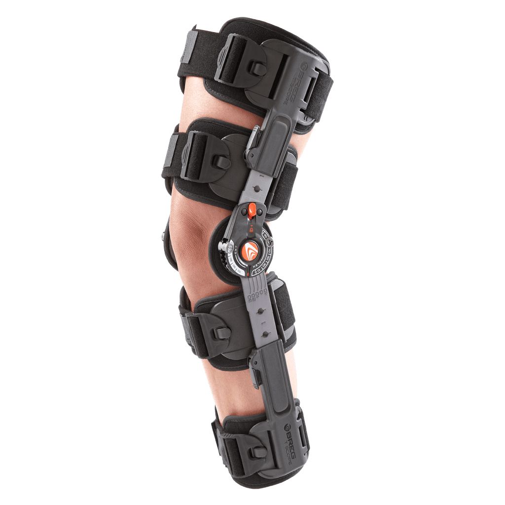
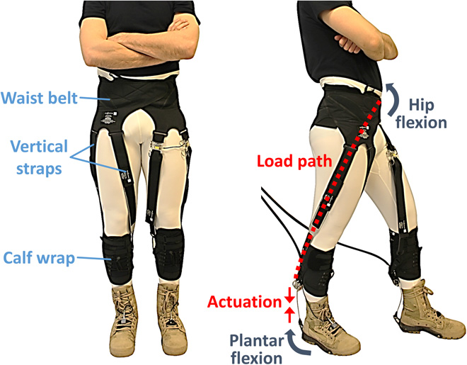
FIG · CONFUSION MATRIX · AI vs PHYSIOTHERAPIST PHYSIOTHERAPIST → ↑ AI CONTINUE INCREASE REDUCE REFER CONTINUE INCREASE REDUCE REFER 15 2 0 0 2 12 0 0 0 1 9 2 0 0 2 5 82% AGREEMENT 41 / 50 sessions
Key finding · E4
All disagreements were between adjacent categories — no AI recommendation ever placed a "continue" patient in the "refer" bin. Errors are calibration, not category.
09Timeline

Sixteen months from biomechanics literature to a working prototype.

2024 · MAY

Literature review · biomechanics & existing devices

Rigid / soft / semi-rigid exoskeleton landscape mapped. Exo-Muscle (Zhang et al., IIT, 2025) identified as the closest reference for the chain mechanism.
2024 · JUL

Tendon routing geometry · MATLAB modeling

Piecewise elliptical-circular routing path calibrated to keep ≥ 3 mm clearance and a smooth moment arm across the 0°–145° range. Fifth-order polynomial fit derived.
2024 · SEP

CAD & first 3D print run

PLA chain links, PETG cuffs, aluminium 6061 rails. Backpack-style hip mount for the DH03X actuator. First donning test in ≤ 45 s.
2024 · NOV

Electronics integration · ESP32 control loop

Dual MPU-6050 IMUs, HX711 load cell, PWM motor driver. Closed-loop torque regulation at 2 Hz; e-stop latch and Bluetooth shipped together.
2025 · FEB

Hardware benchmarking · 9 metrics

Force RMSE 0.8 N (target < 2). Angle RMSE 0.8°. Peak torque 13.5 Nm vs 10 Nm target. All nine scorecard criteria met or exceeded.
2025 · APR

Mannequin trials · six experimental groups

G1–G3 repeatability runs (CV < 2%); G4–G6 condition sweeps. Joint alignment quantified at 1.39 mm mean, 2.55 mm RMS across the full ROM.
2025 · JUN

AI pipeline · DeepSeek integration

Statistical → trend → K-Means → composite scoring → LLM recommendation. 82% categorical agreement with physiotherapists across 50 sessions.
2025 · AUG

Voice submodule · LD3320 offline

"Hey Regenix" wake word, 6 commands, ≥ 95% accuracy in quiet conditions. Cost added: $20. Total BOM: $200.
2026 · planned

Multi-site clinical trial · n ≥ 24

ACL reconstruction, total knee replacement, knee OA. 80% statistical power for clinical efficacy claims. Comparison against home-exercise programmes.
2026 · planned

Regulatory submission · FDA 510(k) · CE

Class II medical device pathway. Target retail price US $300–500 inclusive of 50–67% markup over BOM for community-clinic deployment.
10Outlook

Where this work goes next — improve, deploy, extend.

Short term · 6 months

Refine the device that exists.

  • 01Expand human-subject pilot to n ≥ 24 across ACL, TKR, and knee OA; achieve 80% statistical power for efficacy claims.
  • 02Reduce the 5–8° mechanical lag with cable pre-tensioning and closed-loop force feedback in the Bowden path.
  • 03Add flexible pressure sensors at strap contact points; trigger alerts above 20 kPa to prevent pressure sores.
  • 04Augment AI training corpus with 100+ therapist-reviewed sessions; target 90%+ recommendation agreement.
Long term · 2 years

Deploy where it's needed.

  • 05Solar charging + 5000 mAh battery for > 5 h field runtime in regions with intermittent grid power.
  • 06Telemedicine integration: physiotherapist supervises remotely; rehabilitation data syncs when connectivity allows.
  • 07Multilingual dashboard and voice (English, Spanish, Hindi, Mandarin, Swahili) for global LMIC deployment.
  • 08Randomized controlled trial vs. standard home-exercise; FDA 510(k) and CE submissions; community-clinic pricing at US $300–500.
Application expansion

The chain is a platform.

  • 09Integrate with a low-cost ankle exoskeleton for coordinated lower-limb gait training in post-stroke patients.
  • 10Add EMG and pressure insoles for ACL injury risk assessment in young athletes.
  • 11IMU-driven fall detection for geriatric mobility support; instant assistive torque on fall onset to reduce hip fracture risk.
  • 12Adapt the semi-rigid chain to elbow, shoulder, and ankle joints — a family of ultra-low-cost rehabilitation devices.
Closing note The barrier between five billion people and high-quality rehabilitation is not biological complexity. It is capital cost. This work proposes that, with the right mechanical primitive, a $200 device can deliver clinically meaningful torque, track the joint, and route a personalized program through a single language-model call — without ever leaving the community clinic.